How the TCP/IP Model Actually Works
A CCNA study note breaking down the TCP/IP model layer by layer - protocols, standards, encapsulation, PDUs, and how it compares to the OSI model.
These are my own notes from studying CCNA with Jeremy’s IT Lab. The concepts, examples, and explanations here belong to him - I’m just writing down what I understand as I go, in my own words, so I remember it better. I’ll keep posting notes like this as I work through the course.
The TCP/IP model is the family of protocols that makes communication over the internet - and other networks - possible. It’s a way of grouping network functions based on the job each one does.
In this note I’m going to build that model step by step and use it as a simple map of “who does what” in a network.
Protocols and Standards
A protocol is a set of rules defining how data should be communicated between devices over a network. It’s the “language” computers use to talk to each other. Just like someone who only speaks Chinese can’t talk to someone who only speaks English, two computers “speaking” different protocols can’t exchange data.
In the early days of computer networking, there were several attempts to define the functions computers needed to communicate with each other:
- A protocol was often developed by a specific vendor (e.g. IBM) to be used with their own products.
- With this proprietary approach, enabling communication between different vendors’ products was difficult.
 Apple using its own protocol and IBM using its own protocol means neither can talk to the other - the fix is a common, standardized protocol.
A standard is an agreed-upon specification that describes how a protocol or technology should work. With a vendor-neutral standard, devices of all types can communicate with each other:
- An Apple MacBook can access a website hosted on a web server running Linux.
- A PC running Windows can send an email that gets read on a smartphone running Android.
As long as devices follow the same standard, they can work together on a network.
A Bit of History - How TCP/IP Came About
Early work on the computer network that evolved into today’s internet began in the 1960s, mainly in the US.
- The US Department of Defense’s ARPA (Advanced Research Projects Agency) funded ARPANET, which came online in 1969 to connect mainframes at universities and labs.
- ARPANET originally used a protocol called NCP (Network Control Program).
- In 1974, Vint Cerf and Bob Kahn (working at DARPA) began developing TCP.
- TCP was later split into two protocols: Transmission Control Protocol (TCP) and Internet Protocol (IP).
- Together, these two protocols form the foundation of the protocol suite known as TCP/IP today.
- ARPANET fully switched to TCP/IP on January 1, 1983.
Over time, TCP/IP became dominant over vendor-proprietary solutions because it was published as a set of open standards that any vendor could implement, and it could run over many different types of networks.
Who Actually Defines the Standards
IEEE (Institute of Electrical and Electronics Engineers) develops many of the technologies used on local area networks:
- Ethernet (802.3)
- Wi-Fi (802.11)
IETF (Internet Engineering Task Force) is an open community that defines protocols used on the internet - TCP, IP, UDP, HTTP, DNS, and more. It publishes standards in documents called RFCs (Requests for Comments).
The IEEE and IETF create the standards, and vendors like Cisco implement them so that devices from different companies work together.
Layered Models
Networks do a lot of different jobs to move data from one computer to another - physical transmission of signals, local delivery on a LAN, routing traffic between networks, end-to-end conversations, applications, and more.
A model lets us group related jobs into layers:
- Each layer has a specific role.
- Each layer uses the service of the layer below it and provides services to the layer above it.
- A protocol lives (mostly) at one layer - for example, IP, TCP, or HTTP. Together they form a stack of protocols that work as a team (the network stack).
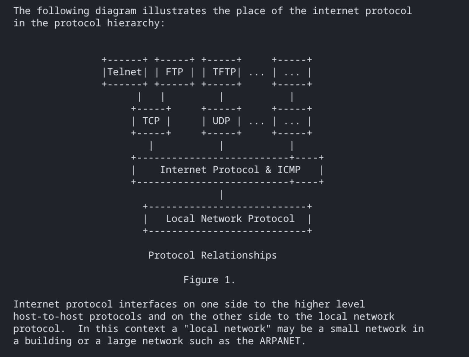 The internet protocol stack
The IP protocol was published in 1981 and is still in use today - if you want to dig deeper, you can read RFC 791.
We can divide the TCP/IP model into a few layers:
- Application Layer
- Transport Layer (TCP, UDP)
- Internet Layer (IPv4, IPv6)
- Link Layer (Ethernet, Wi-Fi)
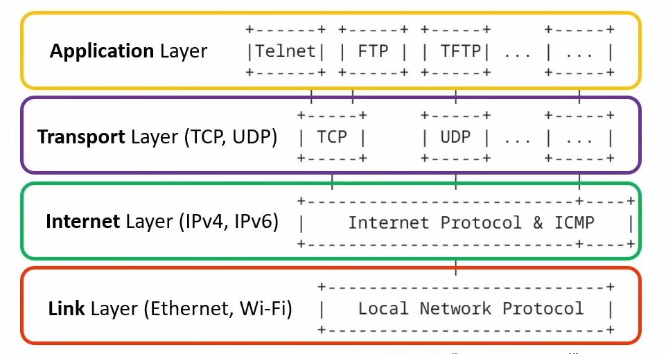 Layers on TCP/IP
This is the TCP/IP model - or at least one version of it. The model is a description, not a law. Different textbooks and courses use different numbers of layers (4-layer, 5-layer, etc). We’ll be using the 5-layer model in this note, and for CCNA.
Let’s Demonstrate It With a Simple Network
Here’s the simple network I’ll use to demonstrate:
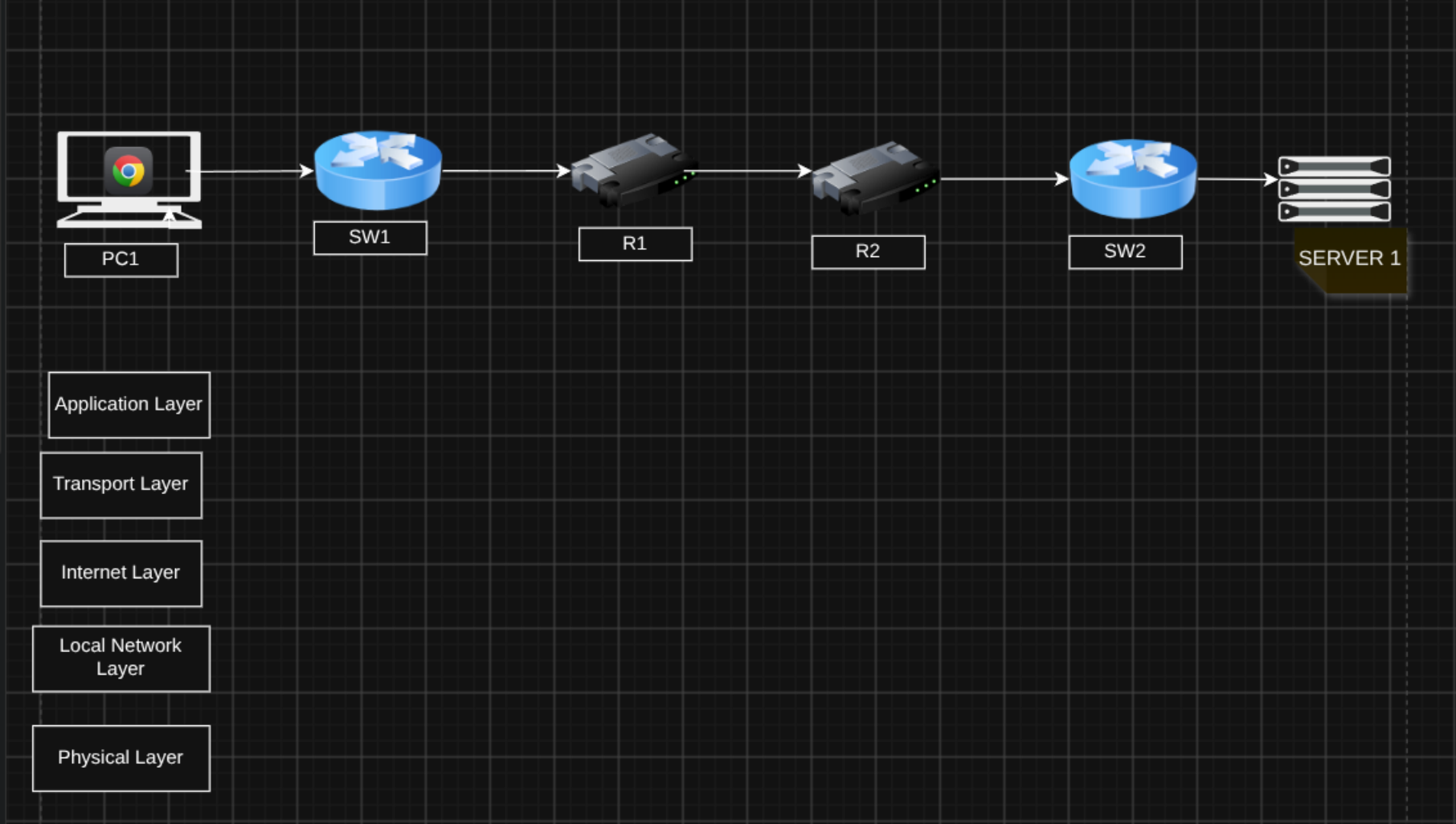 Simple client-server network
- On the left we have PC1, a client that sends requests to Server1 on the right.
- Between them are two routers, R1 and R2.
- SW1 sits between PC1 and R1, and SW2 sits between R2 and Server1.
- PC1 is running a web client application such as Chrome.
- Server1 is running a couple of processes, such as a web server and a file server.
PC1’s user wants to access a webpage hosted on Server1, so the web client on PC1 (Chrome) needs to send a request to the web server on Server1 - that’s the job of the Application Layer.
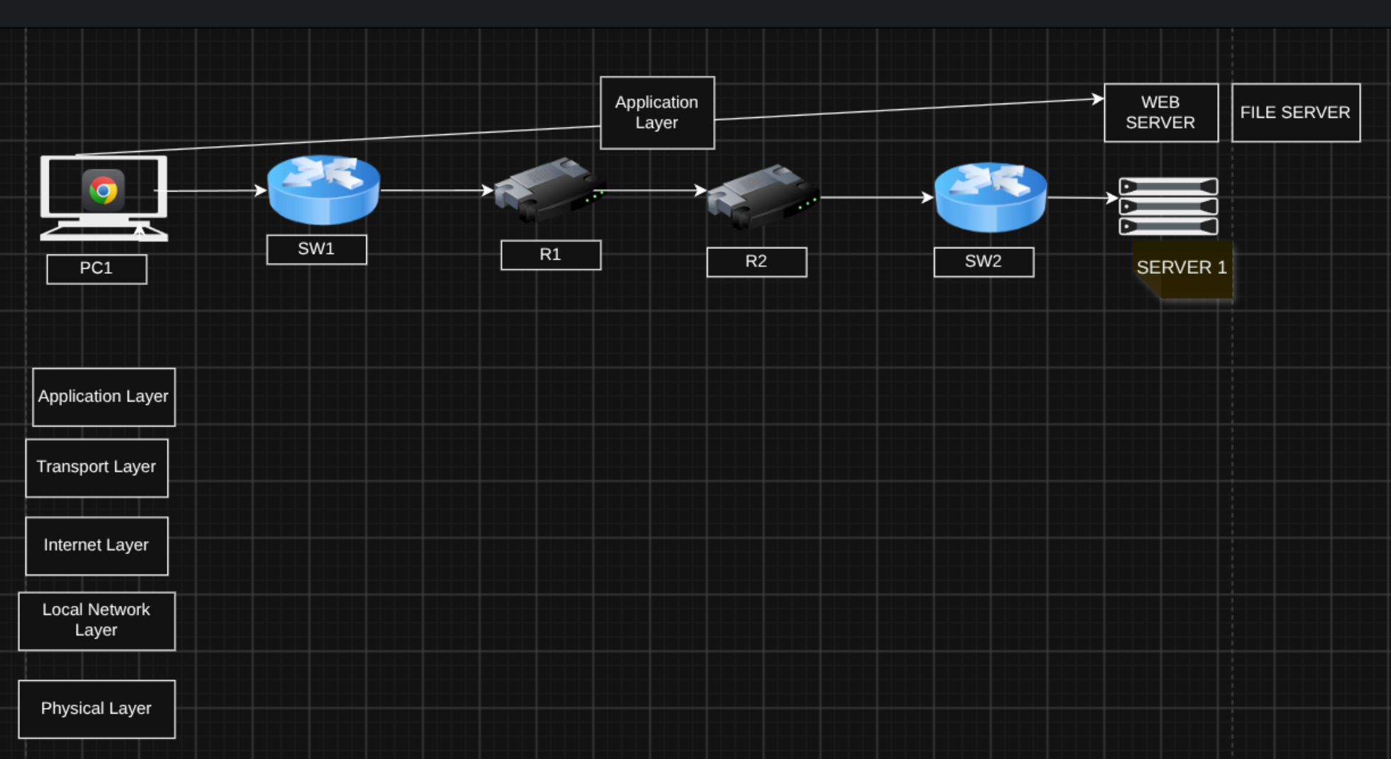 How the Application Layer works
Application Layer: protocols for communication between application processes; they create and interpret the data.
But there’s a problem - there are multiple processes running on Server1 in this figure, a web server process and a file server process, and possibly more in real life. So how can PC1 make sure it’s talking to the correct process on Server1? That’s where the Transport Layer comes in.
Each process on Server1 is associated with a port number - 80 for the web server, 21 for the file server. The important point is that to send a message to the web server, PC1 addresses it to port 80.
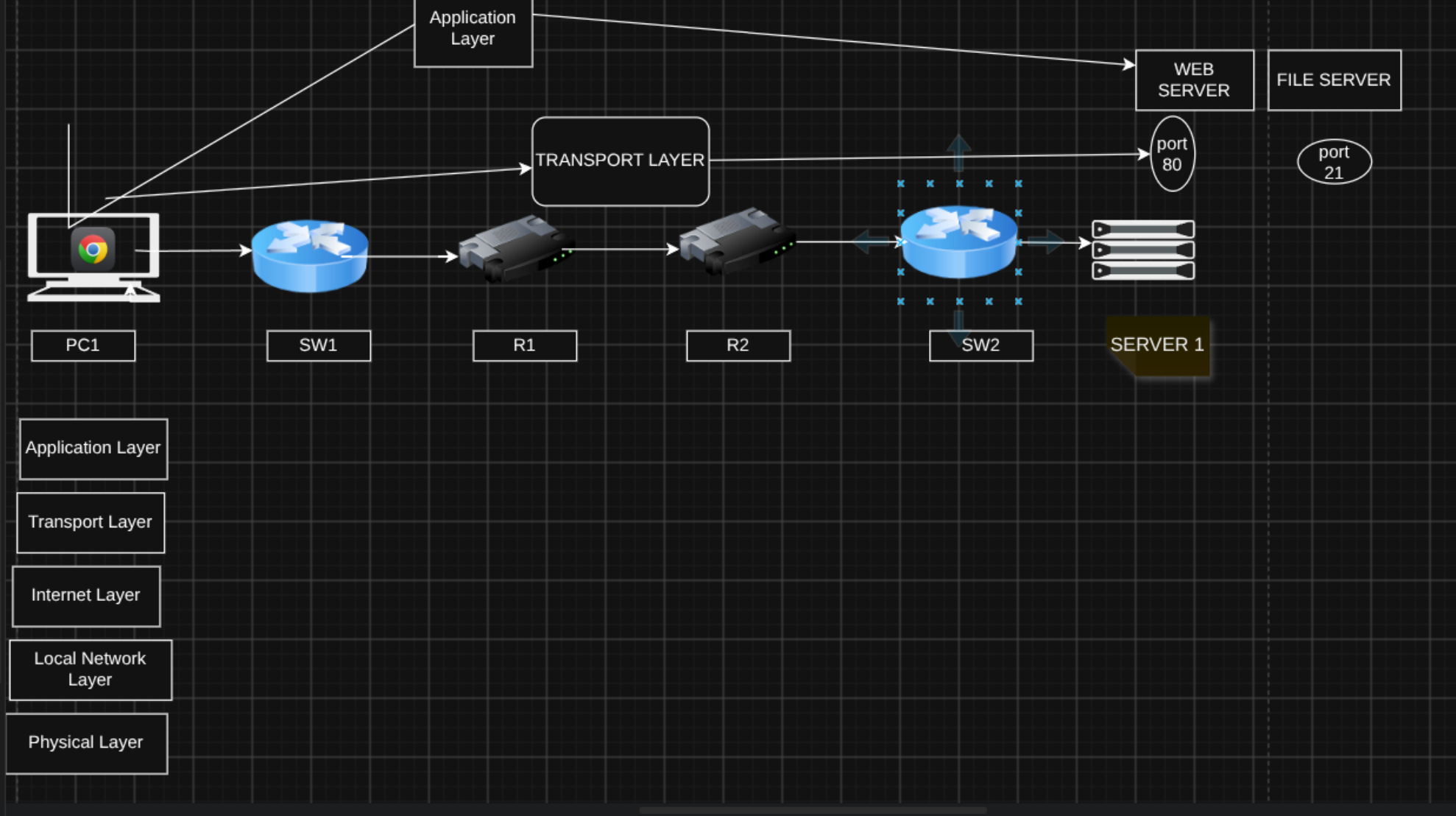 Transport Layer works on ports
A port is just a number that identifies a process running on a host. The role of the Transport Layer is to provide end-to-end communication between application processes using port numbers.
But we still have a problem - even if the message goes to the correct port number, we need to make sure it reaches Server1 in the first place. Server1 has an IP address for that purpose - let’s say the IP of the server is 10.1.1.1.
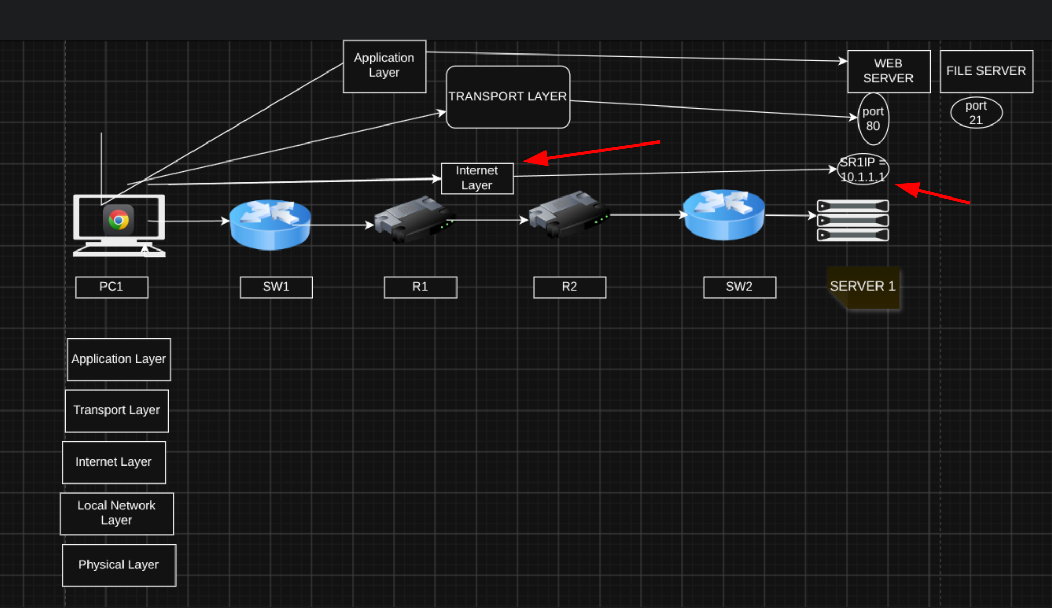 Internet Layer and IP addresses
The Internet Layer provides end-to-end communication between hosts across networks using IP addresses and routers. It gets the message from the source host all the way to the destination host using IP addresses and routers.
When you think of the Internet Layer, just think IP addresses and routers. A host is simply a device connected to the network that can send and receive data - PC1 and Server1 in our example.
Now, there are several devices between PC1 and Server1, and we need to make sure the messages are properly passed along between them - that’s the job of the Local Network Layer.
Using a protocol at this layer such as Ethernet, each device sends the message to the next device on the local network: PC1 → R1 via SW1, R1 → R2, and R2 → Server1 via SW2. The local network layer provides hop-to-hop delivery using MAC addresses and switches.
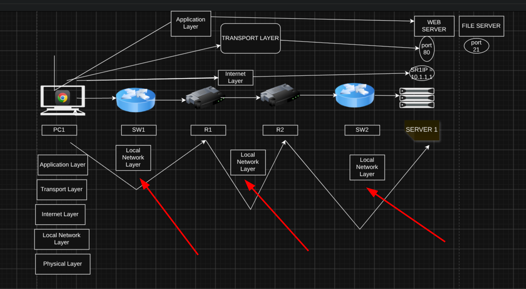 Local Network Layer
The Local Network Layer provides hop-to-hop delivery within a local network using MAC addresses and switches.
So what’s the role of the switches? They connect devices on the LAN and pass messages between them using the specific address of each device.
Last but not least, there’s the Physical Layer - all the cables connecting the devices, plus the transmitters and receivers on each device that send and receive signals. The Physical Layer sends bits as electrical, optical, or radio signals over the physical medium:
- Electrical signals → copper UTP cables
- Optical signals → fiber optic cables
- Radio signals → wireless Wi-Fi connections
Now that we’ve covered the role of each layer at a high level, let’s look at each one in more detail - from the bottom up, starting at the Physical Layer and working toward the Application Layer.
Layer 1 - Physical Layer
The Physical Layer (Layer 1) sends and receives bits as electrical, optical, or radio signals over the medium. It defines things like cables, connectors, signal levels, and link speeds.
Examples: copper UTP cables, fiber optic cable, Wi-Fi radios and antennas, network interface cards (NICs).
The physical aspects of transmitting data are genuinely complex - but network engineers typically don’t need to know the low-level details.
Layer 2 - Local Network Layer
The Local Network Layer (Layer 2) provides hop-to-hop delivery of messages on a local network. A hop is one step along the path between two devices.
So in our figure, when PC1 sends a message to Server1, how many hops are there?
- 1st hop: PC1 → R1
- 2nd hop: R1 → R2
- 3rd hop: R2 → Server1
One thing worth noting - why doesn’t a switch count as a hop? Standard Layer 2 switches don’t count as a hop in networking metrics like traceroute or RIP hop count, because they operate at the Data Link Layer (Layer 2) and forward traffic using MAC addresses without modifying the IP packet’s Time to Live (TTL) value. A switch just extends the local network, allowing multiple devices to connect.
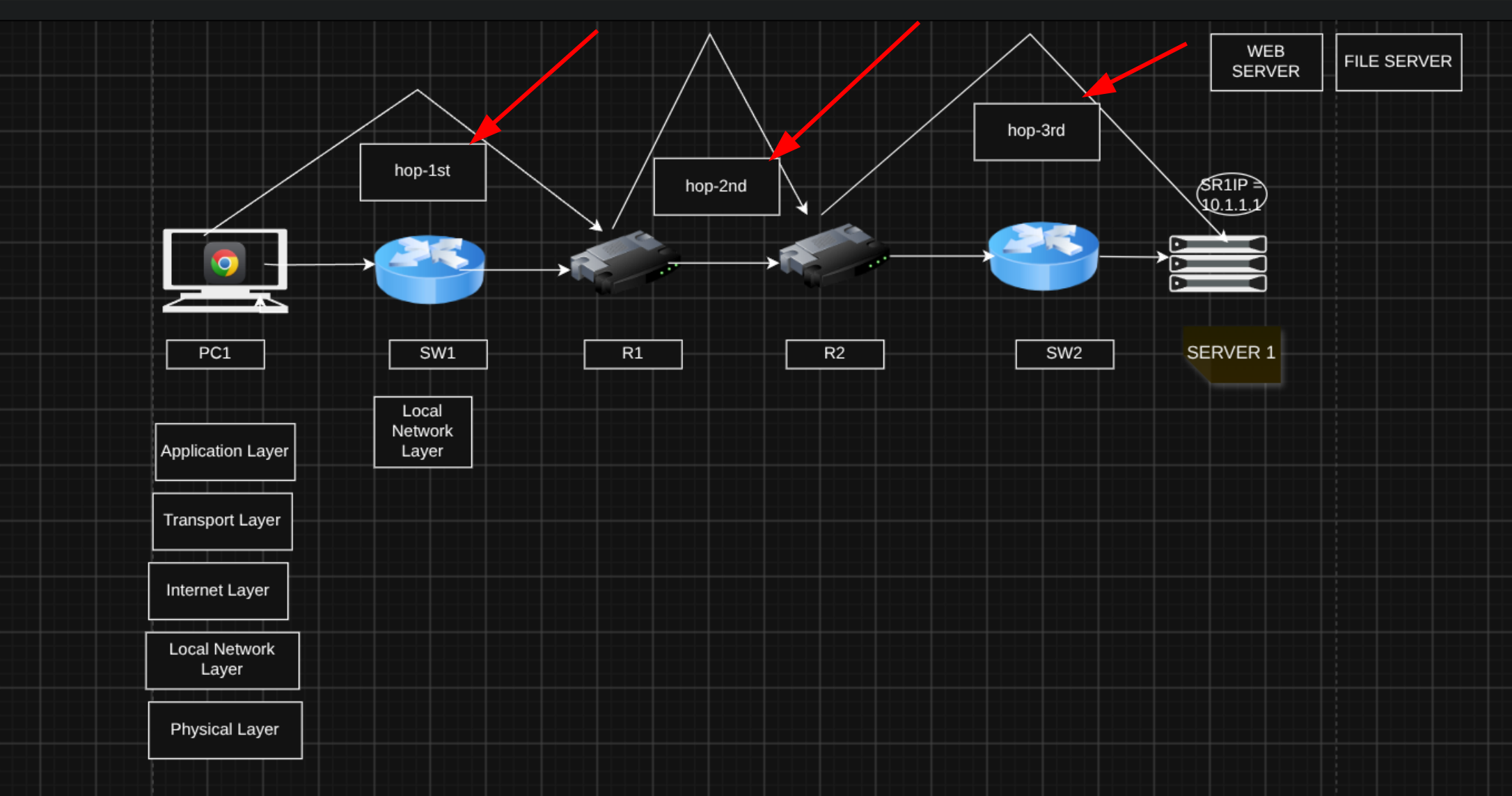 Hop count
Layer 2 uses MAC (Media Access Control) addresses to identify interfaces. Each device connected to the LAN has a unique MAC address for that specific interface.
Since R1 and R2 each have multiple interfaces connected to the network, let’s label them: G1 and G2, for Gigabit Ethernet 1 and Gigabit Ethernet 2 - meaning this interface operates at a speed of 1 gigabit per second.
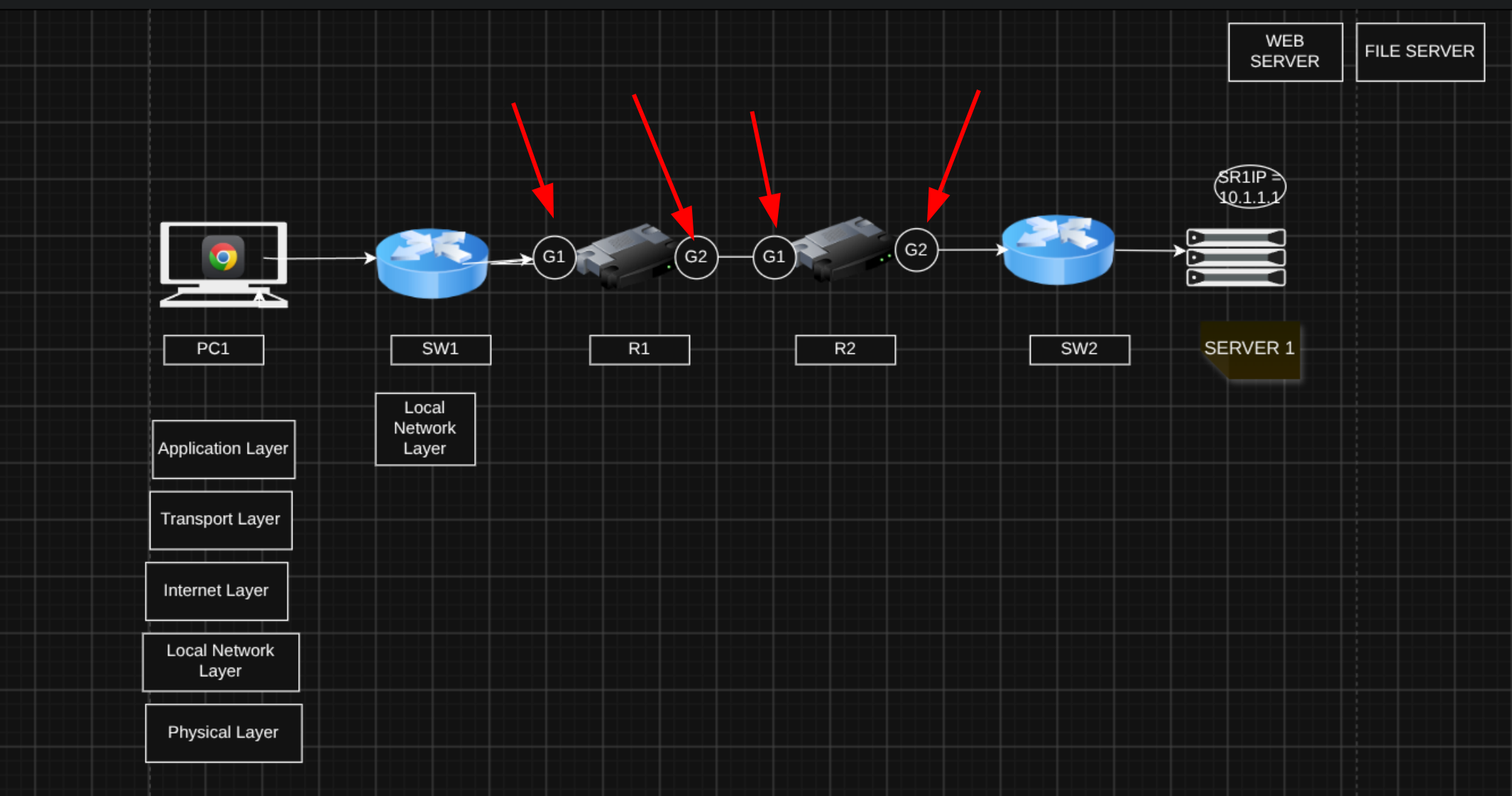 Adding G1 and G2 interfaces on R1 and R2
- PC1 sends the message to the MAC address of R1’s G1 interface (NIC).
- R1 sends the message to the MAC address of R2’s G1 interface (NIC).
- R2 sends the message to the MAC address of Server1’s G1 interface (NIC).
Protocols at this layer include:
- Ethernet (IEEE 802.3)
- Wi-Fi (IEEE 802.11)
Layer 3 - Internet Layer
The Internet Layer (Layer 3) provides end-to-end delivery between hosts across multiple networks. We call it end-to-end because it focuses on getting the message all the way from the source host to the destination host. “Internet” here just means internetwork - between networks.
It uses IP addresses to identify hosts on the network. Let’s say Server1 has the IP address 10.1.1.1 - when PC1 sends a message to Server1, it addresses the message to that IP.
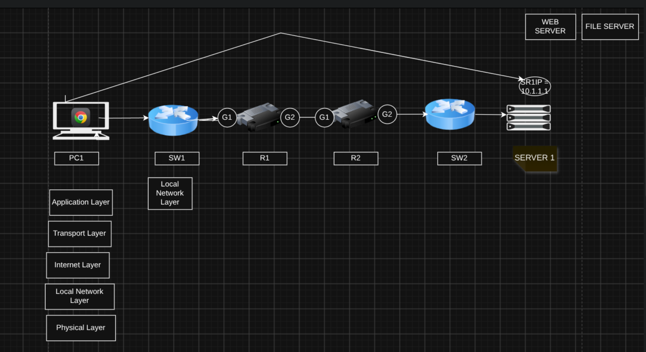 Sends a message to an IP address
Routers operate mainly at this layer, using the message’s destination IP address to forward it toward its final destination host.
Protocols at this layer:
- IP (IPv4, IPv6)
- ICMP (Internet Control Message Protocol)
Layer 4 - Transport Layer
The Transport Layer (Layer 4) provides end-to-end communication between application processes. In our example, Server1 is running multiple services - a web server and a file server - so if Server1 receives a message, it needs to know which service the message is meant for. This is also called process-to-process or service-to-service communication.
This layer uses port numbers to identify the services running on each host - 80 for the web server, 21 for the file server. When the web client on PC1 wants to send a request to the web server on Server1, it addresses the message to port 80. If it were talking to the file server instead, it would address port 21.
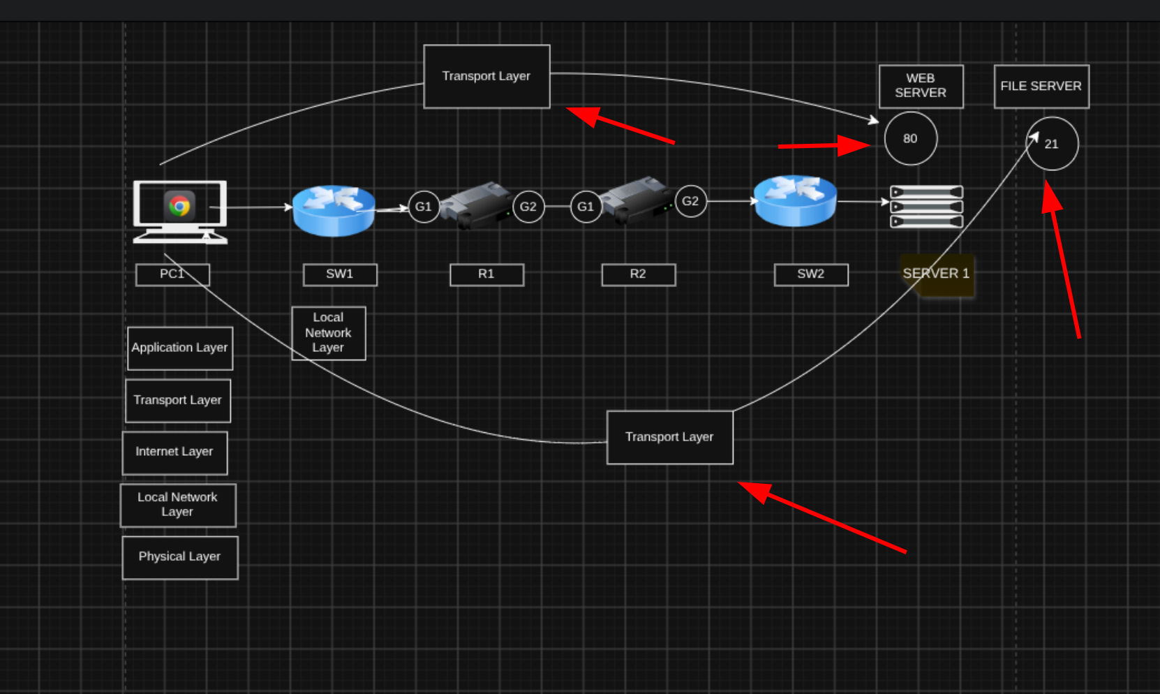 Transport Layer works on ports
This layer runs mainly on the communicating hosts (PC1 and Server1) - routers normally operate based on IP (Layer 3), not transport-layer information, though there are exceptions we’ll cover later.
Protocols used at this layer:
- UDP (User Datagram Protocol): simple and efficient
- TCP (Transmission Control Protocol): more robust, with features beyond basic message addressing
Layer 5 - Application Layer
The Application Layer (Layer 5) is where network communication meets applications. It’s usually called Layer 7 in the OSI model (more on that below). It defines how application processes format, send, and interpret data.
So when Chrome on PC1 sends a message to Server1, it uses an application-layer protocol such as HTTP to format and send that message.
Protocols at this layer define message formats and rules for specific tasks, such as:
- Browsing web pages (HTTP/HTTPS)
- Transferring files (FTP, TFTP)
- Sending/receiving email (SMTP, POP3, IMAP)
Network infrastructure devices (routers, switches) don’t care about application-layer details - they just move messages across the network.
So How Does a Single Message Include All This Layer Info at Once?
That’s where encapsulation and decapsulation come in.
Let’s simplify the network to a direct connection between PC1 and Server1. The Application Layer prepares the data to be sent over the network - for example, an HTTP request that Chrome on PC1 sends to Server1.
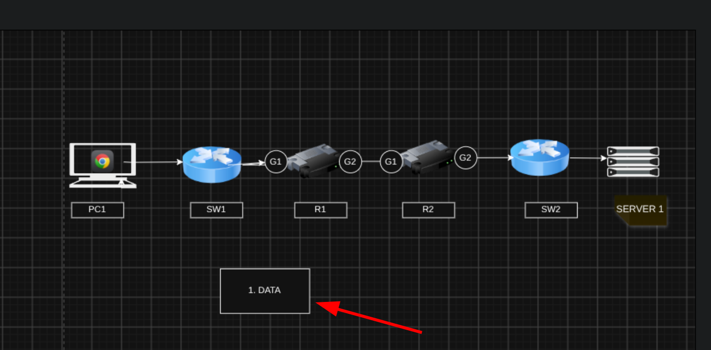 Encapsulation - first step
As the message moves down the stack, each layer encapsulates the data with a header containing the information needed for that layer - for example, source and destination addresses (port numbers, IP addresses, MAC addresses).
First, the Transport Layer encapsulates the data with its own header, including source and destination port numbers and other information.
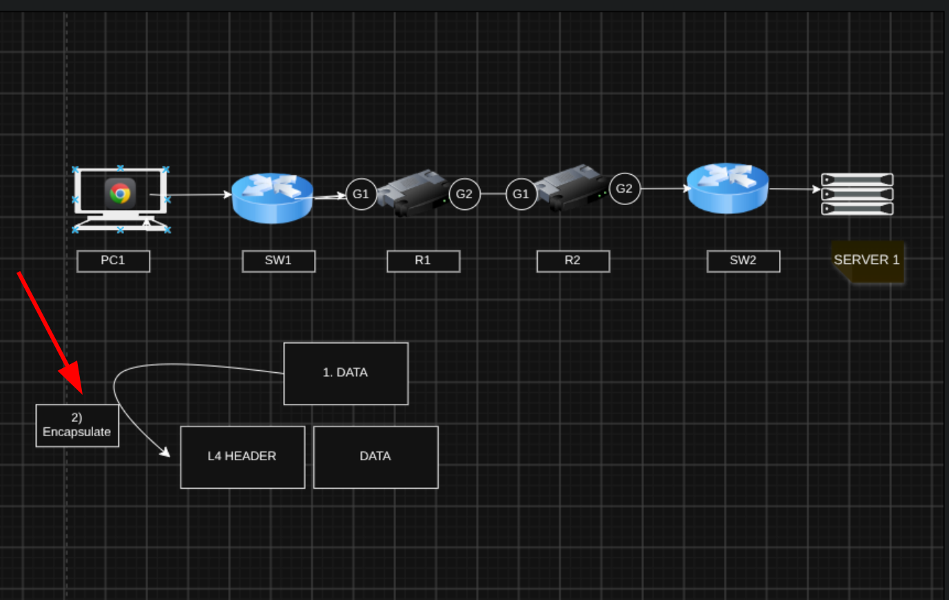 Transport Layer encapsulation
Moving down one more step, the Internet Layer adds its header with the source and destination IP addresses.
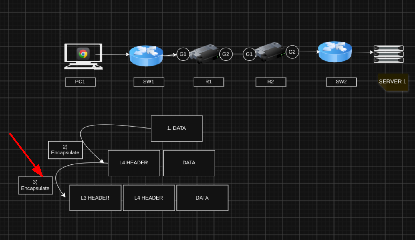 Internet Layer encapsulation
Then Layer 2 encapsulates the data with both a header and a trailer - the trailer is used by the receiving device to check for transmission errors.
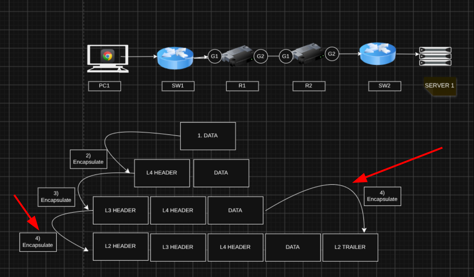 Layer 2 encapsulation
Finally, the Physical Layer transmits the signal over the physical medium - an Ethernet cable, in this case.
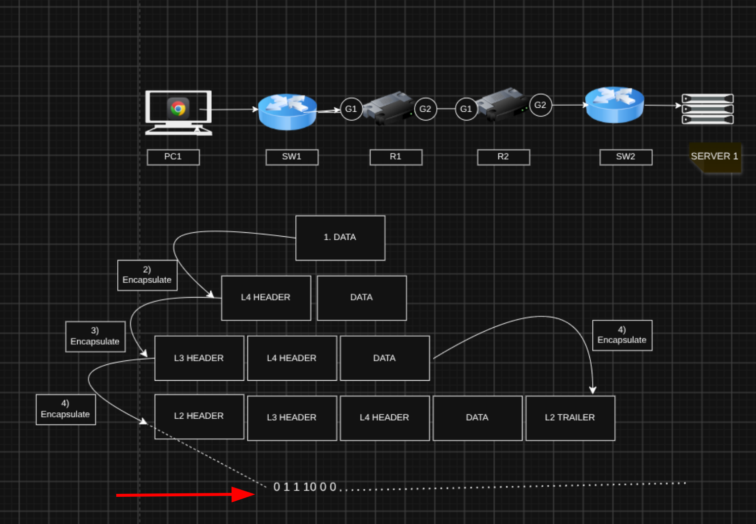 Physical Layer encapsulation
That’s the encapsulation process overall - now let’s look at decapsulation.
Decapsulation
Decapsulation is the reverse of encapsulation. Here’s an image to make it click a bit more easily:
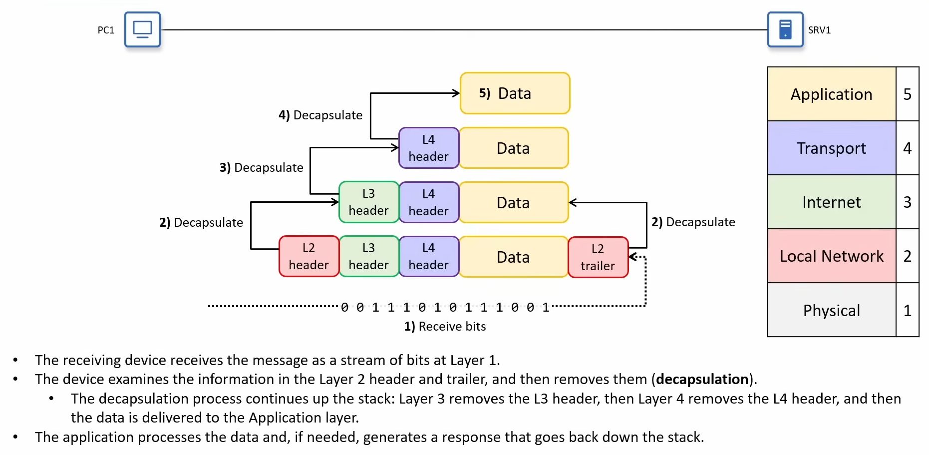 Decapsulation process
Protocol Data Units
At each stage of the encapsulation/decapsulation process, the message gets a different name.
The combination of data and an L4 header is called a segment (TCP) or a datagram (UDP). Worth remembering: TCP creates segments, UDP creates datagrams.
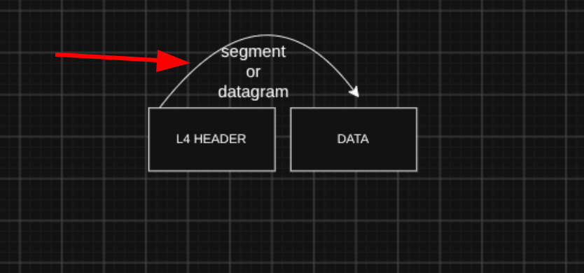 Segment or datagram
The combination of a segment/datagram and an L3 header is called a packet.
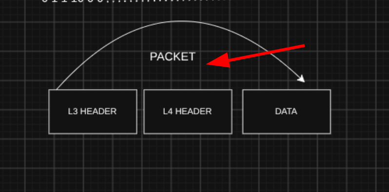 Packet
The combination of a packet and an L2 header/trailer is called a frame - this is what’s actually sent over the wire.
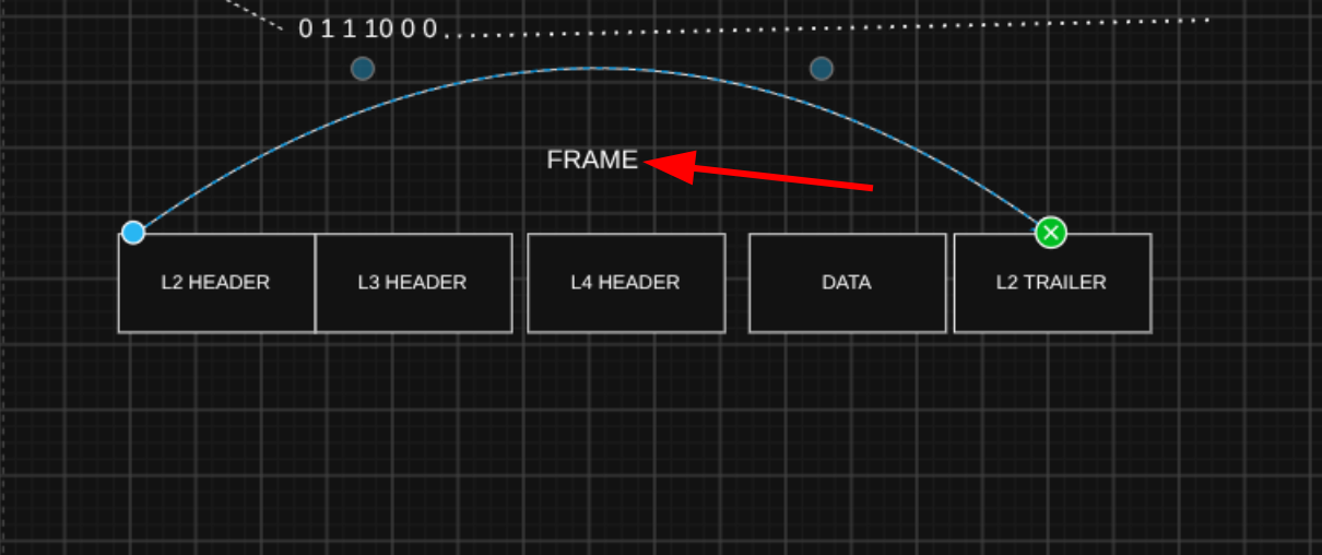 Frame
Frame
We can also describe the message at each stage using an alternate name: Protocol Data Unit (PDU).
- A segment or datagram is a Layer 4 PDU (L4 PDU).
- A packet is a Layer 3 PDU (L3 PDU).
- A frame is a Layer 2 PDU (L2 PDU).
The contents of each PDU (everything encapsulated by that layer’s header/trailer) is called the payload:
- A segment or datagram’s payload is the application data.
- A packet’s payload is a segment or datagram.
- A frame’s payload is a packet.
Layer Interaction
- Each layer provides a service to the layer above it, and is serviced by the layer below it (adjacent-layer interaction).
- Each layer communicates with the same layer on other devices (same-layer interaction).
The OSI Model
TCP/IP development started in the 1970s (ARPANET work, early TCP/IP specs). In the late 1970s and 1980s, the International Organization for Standardization (ISO) designed a 7-layer Open Systems Interconnection (OSI) model and a matching protocol suite.
OSI’s protocols ended up arriving late and being overly complex, and never gained the same real-world deployment as TCP/IP - TCP/IP won, although some OSI concepts are still in use today.
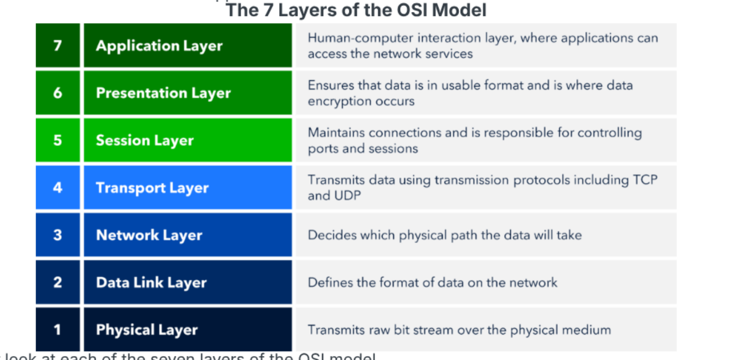 The OSI model
Today, almost every real network uses TCP/IP, but the 7-layer OSI model survives as a reference/teaching model and a common way to talk about “layers.”
Most networking resources use a 5-layer model:
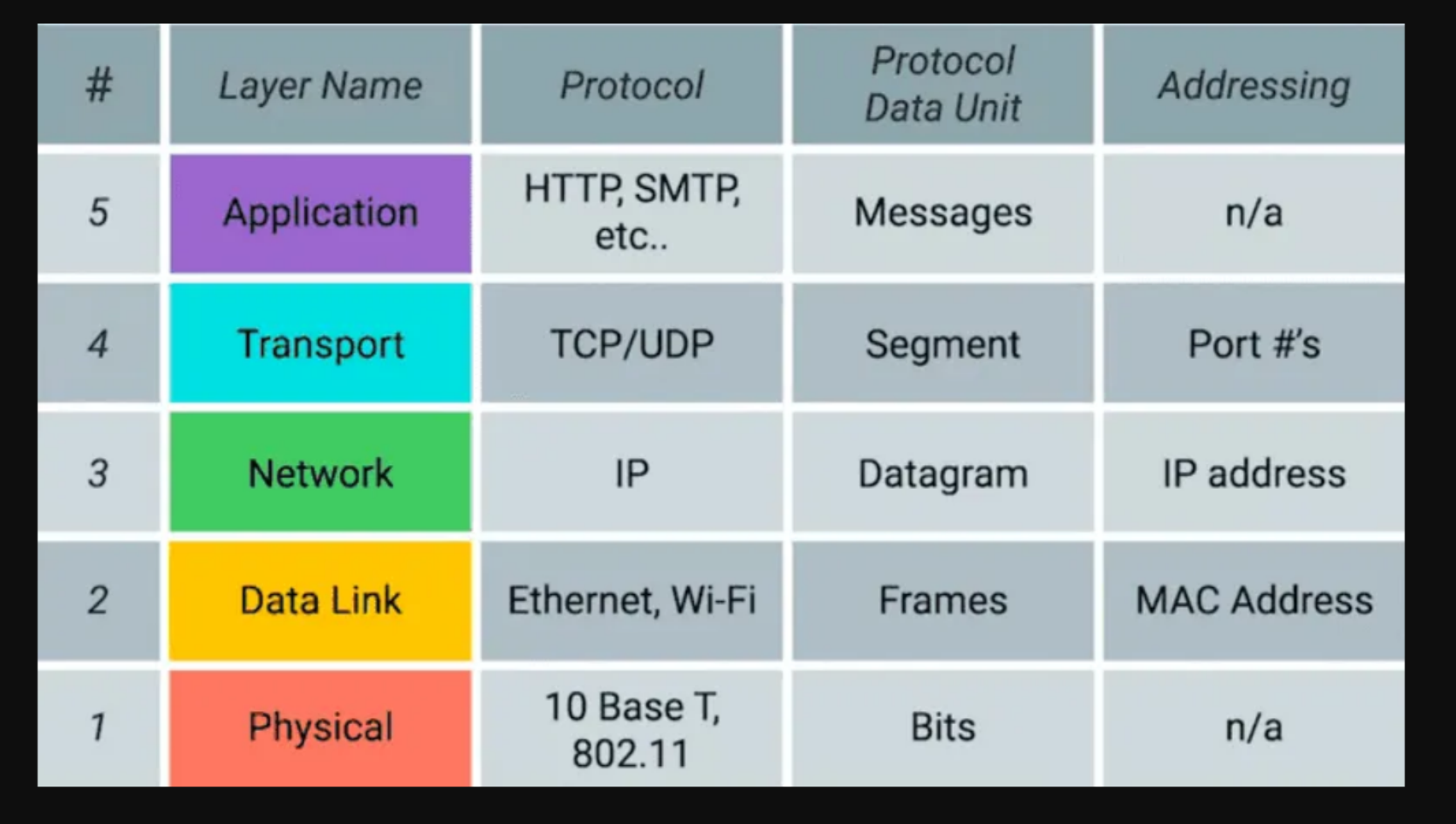 The 5-layer TCP/IP model
The Application Layer is often called Layer 7 in TCP/IP too, since it’s a mix of the OSI model’s Session and Presentation layers.